DISCOWER Propeller Plate
This page is a work-in-progress
The second layer in the free-flyer is the actuation plate. This layer is a modular component that provides propulsion via brushless motors and propellers, but which can also be switched for other actuator models. Below, you can see the 3D model of the propeller plate with 4 motors.
1. Mechanical Assembly
Platform Compatibility
The propeller plate is designed as a drop-in alternative to the thruster plate: it shares the same standoff and mounting interface on the free-flyer, so either one can be installed on its own depending on your propulsion needs. If a thruster plate is installed, it must be installed directly above the base plate so it can be easily connected to the compressed-air supply. The 3D model below shows both plates mounted together.
Actuation Support Plate (Middle Plate)
First, start by cutting with a water jet the actuation support plate, item 0101 in the Bill of Materials. The plate is 8mm thick and has a diameter of 400mm. The DXF file for the plate can be downloaded here, and the end result can be seen in the 3D model below.
Actuation Plate
Then, we can waterjet the actuation plate that will host the motor brackets. This plate’s geometry is specific to the propeller configuration - it is shaped to mount the four motor brackets in their planar layout — but it attaches to the middle plate the same way as the thruster variant: using 8 standoffs, item 0107, and 8 M5 screws. The DXF file for it can be downloaded below. The assembly can be seen in the 3D model below.
Motor Modules
Bracket
At this stage, we are ready to assemble the motor modules. We will provide instructions for one such module, knowing that the procedure can be repeated for the other three. To start, print the custom 3D printed bracket provided with the link below.
Motor and Propeller Assembly
Next, mount the Velox Veloce V2208 V2 motor onto the bracket using its included mounting screws, then attach the Gemfan 3545 propeller to the motor shaft and secure it with the propeller nut. The completed motor module can be seen in the 3D model below.
Aluminium Profiles
Lastly, install the aluminium profiles in the middle plate. Each aluminium profile should have a length of 15cm. The profiles are attached to the plate using M4 screws and nuts. The assembly can be seen in the 3D model below. At this stage, your propeller plate is complete.
2. Electronics Wiring
Motor Driver and CAN Bus
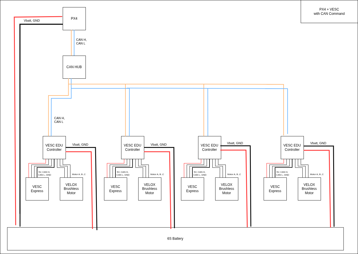
Each motor is driven by its own VESC 6 EDU controller, for four VESCs in total. Connect the four VESCs to PX4 through a CAN hub with four outputs for the VESCs and one input from PX4. The Holybro CAN HUB listed in the BOM is one example; other hubs with the required connections can also be used.
Wiring Diagram
After assembling each motor module, wire the corresponding VESC 6 EDU controller to power and to the CAN bus as follows. Each VESC takes power directly from the battery, and shares its CAN H / CAN L pair with the CAN hub. The table below summarizes the per-motor wiring.
| Motor | Driver | Power Connection | CAN Connection |
|---|---|---|---|
| M1 | VESC 1 | VESC power input → XT60 Power Distribution Module | CAN H / CAN L → CAN HUB |
| M2 | VESC 2 | VESC power input → XT60 Power Distribution Module | CAN H / CAN L → CAN HUB |
| M3 | VESC 3 | VESC power input → XT60 Power Distribution Module | CAN H / CAN L → CAN HUB |
| M4 | VESC 4 | VESC power input → XT60 Power Distribution Module | CAN H / CAN L → CAN HUB |
The CAN HUB aggregates the four CAN H / CAN L pairs coming from the VESC controllers into a single pair, which connects directly to the CAN port on the PX4 flight controller. No PWM wiring is required for this configuration, since motor commands are sent over CAN.
Below 3D view illustrates each motor module (M1-M4). Refer to it for correct placement and orientation when wiring.
3. Software Setup
Before starting this section, complete the Pixhawk Setup.
VESC Programming
Use VESC Tool Free and load these CAN configuration files onto each VESC:
- VESC Tool Free: Download
- Motor Configuration File: vesc_mcconf.xml
- App Configuration File: vesc_appconf.xml
Safety Warnings
- REMOVE THE PROPELLER: If possible, do not perform these setup steps with a propeller attached to the motor. Unexpected throttle spikes during configuration can cause severe injury or damage equipment.
- BEWARE THE GRID GROUND LOOP: If your PC and your VESC are both grounded to the wall grid, massive currents can travel through the USB cable and destroy your hardware. Always run your laptop on battery power (unplug the charger from the wall) when connecting via USB to a live VESC.
- Ground loop diagram: VESC_GroundLoop.png
- More on the ground loop: VESC Documentation
Configure the VESCs
Connect to the VESC
- Ensure you have read and acknowledged the safety warnings above.
- Power the VESC by plugging in the main 6S battery.
- Connect the VESC to your computer using the Micro-USB cable. (Verify your laptop charger is unplugged!)
- Open the VESC Tool on your computer.
- Click the Connect button in the VESC Tool (usually auto-detects the COM port) to establish a connection with the VESC.
Load the Configuration Files
Instead of running the manual setup wizards, we will load pre-calibrated XML files for the motor parameters and app routing (Specific to use with the T-Motor VELOX V2208 V2).
- Load Motor Config:
- Navigate to
File->Load Motor Configuration XML. - Select your downloaded Motor Config XML file.
- Click the Write Motor Configuration button (the ‘M’ down-arrow icon on the right toolbar) to flash these settings to the VESC.
- Navigate to
- Load App Config:
- Navigate to
File->Load App Configuration XML. - Select your downloaded App Config XML file.
- Click the Write App Configuration button (the ‘A’ down-arrow icon on the right toolbar) to flash these settings to the VESC.
- Navigate to
PX4 Airframe and Actuator Setup
Follow the airframe-selection step in Pixhawk Setup, selecting KTH-ATMOS-DUAL instead of KTH-ATMOS. This airframe includes both the DISCOWER thruster plate and the propeller plate. If you are building only the propeller plate, remove the thrusters from the airframe configuration.
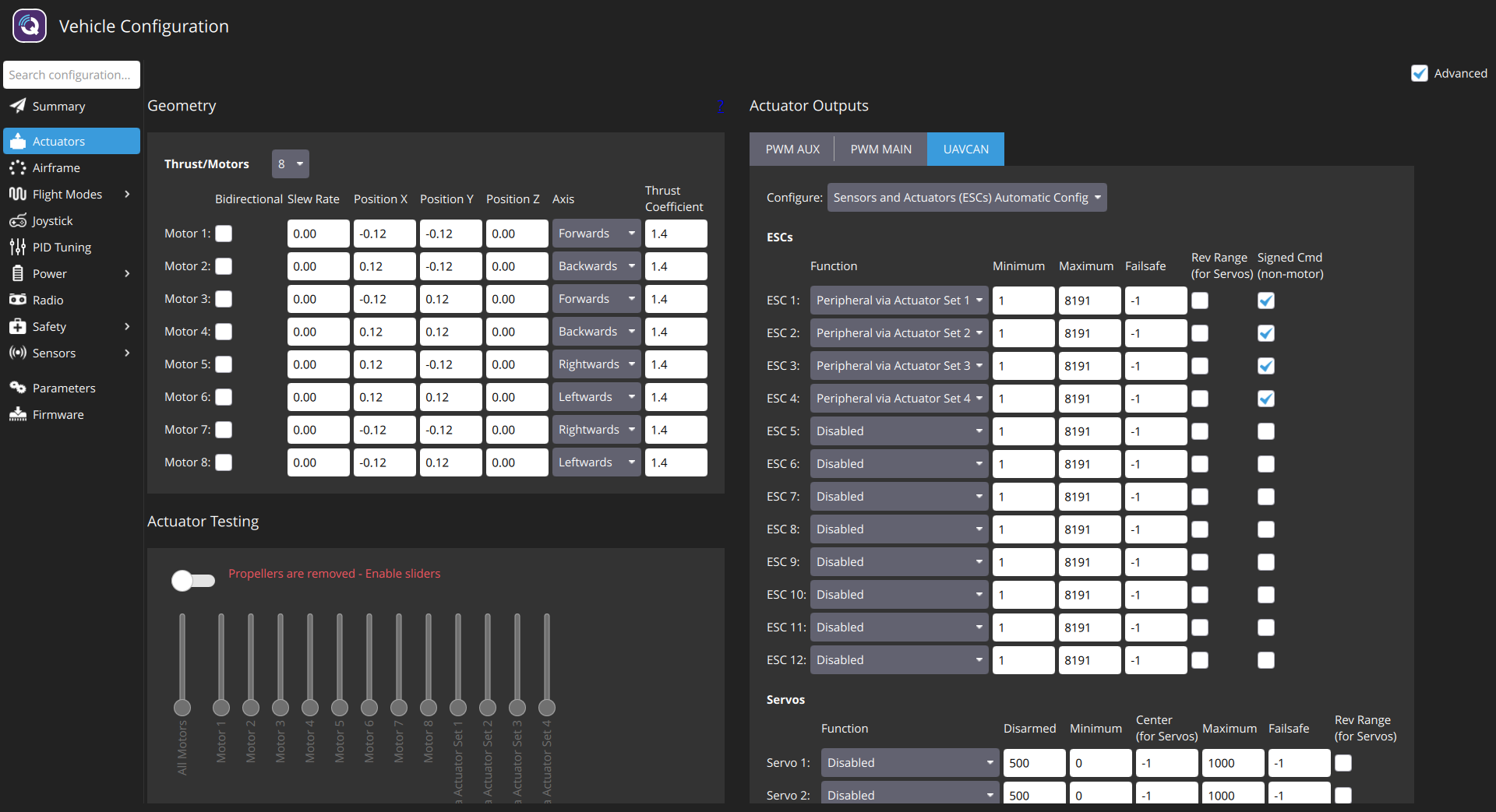
In QGroundControl, open Vehicle Setup -> Actuators and select the UAVCAN tab. Check Advanced in the top-right corner to show the Signed Cmd setting. Configure ESC 1-4 as follows:
| ESC | Function | Minimum | Maximum | Failsafe | Signed Cmd |
|---|---|---|---|---|---|
| 1 | Peripheral via Actuator Set 1 | 1 | 8191 | -1 | TRUE |
| 2 | Peripheral via Actuator Set 2 | 1 | 8191 | -1 | TRUE |
| 3 | Peripheral via Actuator Set 3 | 1 | 8191 | -1 | TRUE |
| 4 | Peripheral via Actuator Set 4 | 1 | 8191 | -1 | TRUE |
Propeller Command Directions
Use the FLU (Forward, Left, Up) body frame. As shown in the figure, each propeller’s center of thrust is 105 mm from the ATMOS geometric center along the associated body axis. Because thrust acts away from the center, it also creates torque about the center.
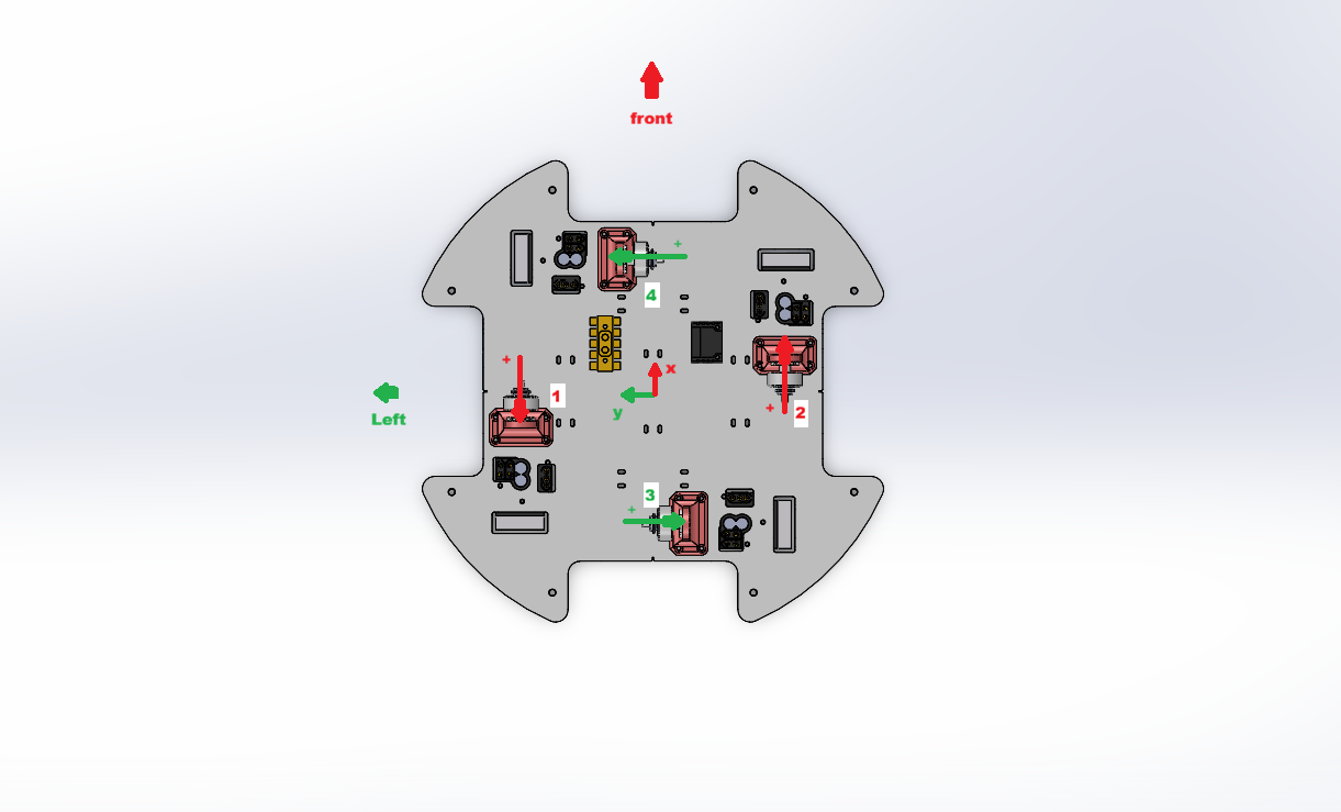
For a positive command, each motor produces the following body-frame force and torque:
| Motor | Body force | Body torque |
|---|---|---|
| 1 | -X | +Z |
| 2 | +X | +Z |
| 3 | -Y | +Z |
| 4 | +Y | +Z |
The maximum force is approximately ±1.8 N per propeller with the supplied VESC limits. This limit depends on the VESC configuration and can be increased.
ROS 2 Communication
Before continuing with this section, complete the Onboard Computer Setup.
To command the propellers directly, publish px4_msgs/msg/VehicleCommand messages on /fmu/in/vehicle_command. Parameters param1 through param4 command motors M1 through M4, respectively. Each parameter accepts a command in the range [-1, 1]; negative values command reverse thrust.
As with any ROS 2-based control of ATMOS, the free-flyer must be armed and in OFFBOARD mode. Maintain OFFBOARD mode by continuously publishing px4_msgs/msg/OffboardControlMode messages to /fmu/in/offboard_control_mode.
For force-based control, we recommend the DISCOWER propeller plate interface package. Its ROS 2 node subscribes to /prop_plate/external_motor_cmd with message type std_msgs/msg/Float32MultiArray and publishes the corresponding commands to /fmu/in/vehicle_command. Send an array of four requested propeller forces in Newtons, ordered M1 through M4.
Force does not map linearly to command. The package includes a measured calibration for this mapping, which may differ for your motors and propellers.
After completing the ROS 2 setup, use ROS 2 commands to test the motors and verify their directions against the table above.
Verify VESC Operation
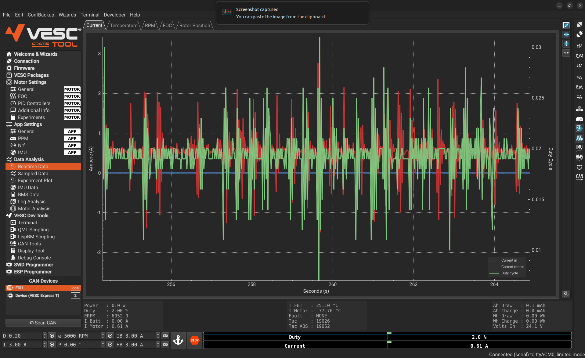
After completing the PX4 and ROS 2 setup, use VESC Tool to verify the commanded motor states and monitor live telemetry.
- In VESC Tool, open RT APP (Real-Time App Data). Enable Stream Real Data if you need additional live data.
- To view current, temperature, RPM, and other live values, open Data Analysis -> Realtime Data.