Actuation Plate
The second layer in the free-flyer is the actuation plate, a modular component that provides thruster capabilities via solenoid valves, but which can also be switched for other actuator models such as. Below, you can see the 3D model of the actuation plate with 8 thrusters, two in each thruster module. Each module houses two solenoid valves, that will be later controlled by the onboard PX4.
Actuation Support Plate (Middle Plate)
First, start by cutting with a water jet the actuation support plate, item 0201 in the Bill of Materials. The plate is 8mm thick and has a diameter of 400mm. The DXF file for the plate can be downloaded here, and the end result can be seen in the 3D model below.
Actuation Plate
Then, we can waterjet the actuation plate that will host the thrusters. The DXF file for it can be downloaded below. The actuation plate is attached to the middle plate using 8 standoffs, item 0107, and 8 M5 screws. The assembly can be seen in the 3D model below.
Thruster Modules
Module Base
At this stage, we are ready to assemble the thruster modules. We will provide instructions for one such module, knowing that the procedure can be repeated for the other three. Note that the actuation modules are 2 original format and 2 mirrored units. To start, print the housings provided with the link below.
First Solenoid
Then, we can install the first solenoid with the 4-to-2mm adapter, as well as the 2mm tubing (items 0209, 0211, 0216). The solenoid is attached to the housing using the provided 3D printed part that is secured with M2 screws. The assembly can be seen in the 3D model below.
Second Solenoid
Then, we can install the second solenoid, on top of the first one, as shown in the visualization below. The items used are 0209, 0211, and 0216. The solenoid is attached to the housing using the provided 3D printed part that is secured with M2 screws. The assembly can be seen in the 3D model below.
Power and Signal Distribution PCB
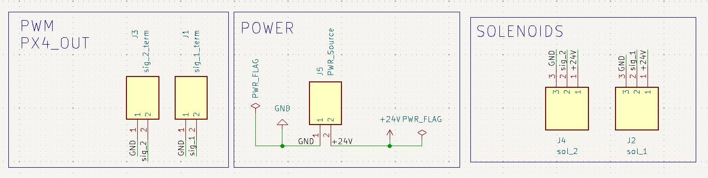
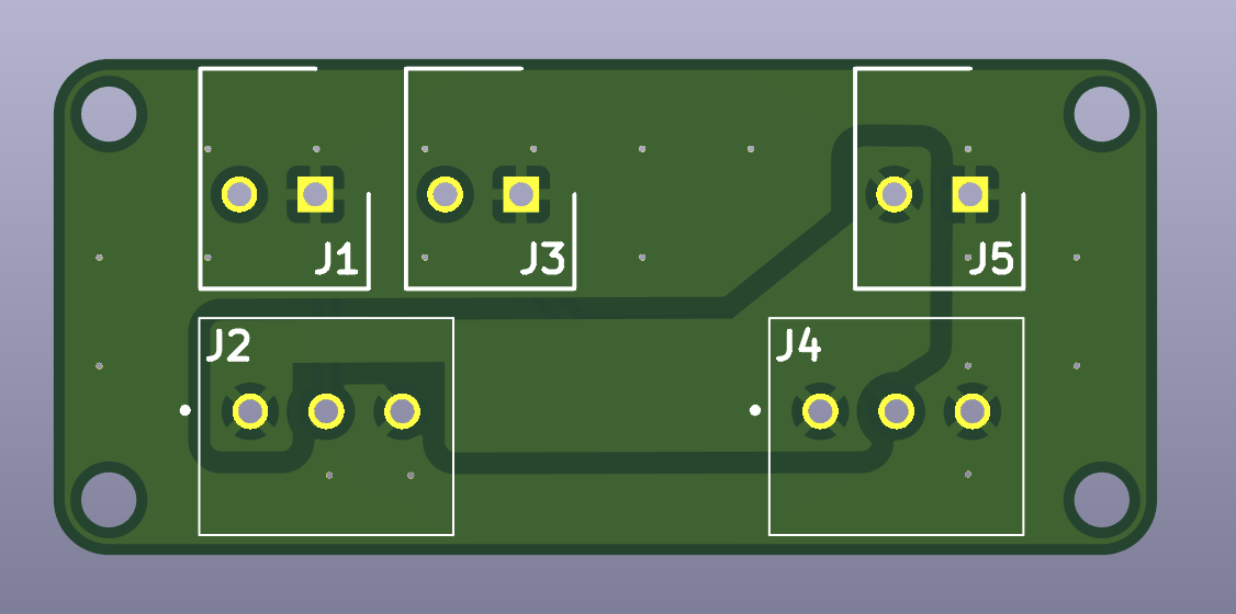
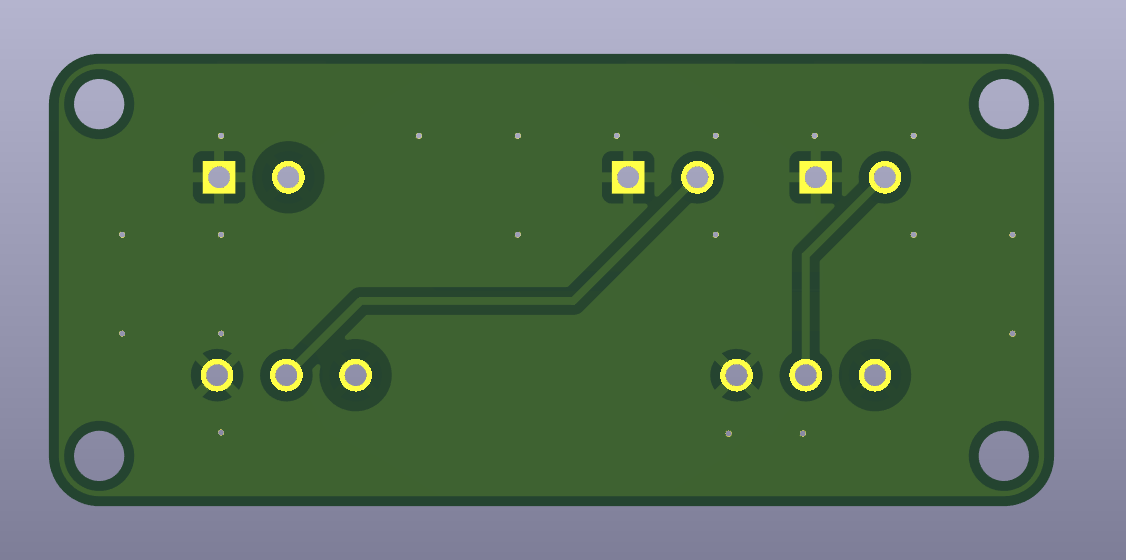
Now we are ready to install the power and signal distribution PCB on the side of the thruster module, as shown below. The PCB is composed of items 0010 and 0011. The PCB is attached to the housing using 2 M2 screws and nuts. The assembly can be seen in the 3D model below.
The pictures below show the PCB’s front and back, as well as the schematic view.
Gerber Files
Gerber files for this PCB will soon be made available for easy fabrication.
Power Regulator and Top Cover
With the bottom part finished, we can now install the power regulator on the top cover. The power regulator is item 0003 and it is attached to the top cover (3D printed with the STL below) with two M5 screws and nuts. The assembly can be seen in the 3D model below.
Thruster Module Assembly
The last step is to attach the top cover using M3 screws and nuts, as per the assembly below.
Thruster Module Wiring
After assembling each thruster module, the next step is to connect the power regulator and the thrusters’ solenoids to the on-board PCB and the Pixhawk’s PWM breakout board.
The power regulator provides a stable 24V output for the thruster solenoids and other module electronics. It has four wires, connected as:
Input (9-40 V): Connect to the main power source.
Input GND: Connect to the main supply ground.
Output (+24 V, 6 A): Provides regulated 24V to the thruster PCB. Connect to J5.
Output GND: Provides ground reference to the thruster PCB. Connect to J5.
Here, Input and Output refer to the input and output of the power regulator.
Each thruster (T1-T8) is connected to a corresponding pair of terminals on the PCB, which then routes the signal to the Pixhawk PWM breakout board. The table below summarizes the thruster wiring.
| Thruster | Module | Force Direction* | PCB Connections |
|---|---|---|---|
| T1 | M1 | +X | Solenoid → J2 → J1 → PWM1 |
| T2 | M2 | -X | Solenoid → J4 → J3 → PWM2 |
| T3 | M3 | +X | Solenoid → J4 → J3 → PWM3 |
| T4 | M4 | -X | Solenoid → J2 → J1 → PWM4 |
| T5 | M2 | +Y | Solenoid → J2 → J1 → PWM5 |
| T6 | M4 | -Y | Solenoid → J4 → J3 → PWM6 |
| T7 | M1 | +Y | Solenoid → J4 → J3 → PWM7 |
| T8 | M3 | -Y | Solenoid → J2 → J1 → PWM8 |
*Direction using the coordinate frame of the Pixhawk controller, i.e. X-forward, Y-right, Z-down.
Below 3D view illustrates each thruster (T1-T8) and thruster module (M1-M4). Refer to it for correct placement, orientation and wiring.
Actuator Plate and Pneumatic Connection
With all thruster modules assembled, it is time to install them on the plate and do all the power and pneumatic connections. For the pneumatic connections, please follow the diagram in the 3D model below, connecting the same letters to the same spots (that is A-A, B-B, etc). The power connections from the power regulators should be connected to the power hub in the actuation plate (item 0008) using power cables capable of passing a peak of 4A. Lastly, connect the PWM cables (item TODO) to the PX4 mini PWM receptor.
Aluminium Profiles
Lastly, install the aluminium profiles in the middle plate. Each aluminium profile should have a lenght of 12cm. The profiles are attached to the plate using M4 screws and nuts. The assembly can be seen in the 3D model below- At this stage, your middle plate is complete.